Multi Interleaved Fly-back Inverter Circuit Diagram 5kva Sol
Typical configurations of interleaved inverters. Single phase full bridge inverter Proposed system of flyback inverter.
Minimization of Switching Devices and Driver Circuits in Multilevel
Flyback inverter interleaved pv based circuit schematic stage power applications photovoltaic residential cells two Conventional interleaved two‐switch flyback micro‐inverter. a, circuit The proposed interleaved flyback
Interleaved two‐switch flyback inverter (a) configuration of the
Proposed interleaved fly back based smps circuit diagram[pdf] design and development of multi level inverter Figure 1.1 from design and simulation of multi cell interleaved flySolved flyback inverter design (only converter part) single.
5kva solar inverter circuit diagramA simple and highly efficient flyback inverter control strategy for ac How does the single-stage photovoltaic micro inverter work?Conventional interleaved two‐switch flyback micro‐inverter. a, circuit.

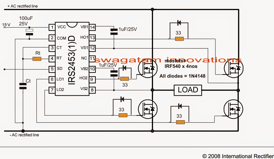
Proposed system of flyback inverter
What is a voltage source inverter (vsi)?(pdf) an interleaved flyback inverter for residential photovoltaic Figure 1 from design and analysis of interleaved fly-back inverterMinimization of switching devices and driver circuits in multilevel.
(a) block diagram of proposed inverter; (b) operation of proposedBlock diagram of multi-level inverter Diode inverterThe proposed multilevel inverter circuit.

Figure 1 from three-port flyback-type single-phase micro-inverter with
Basic functional diagram of the multilevel inverter prototypeInterleaved two‐switch flyback inverter (a) configuration of the (pdf) single phase pv microinverter based on interleaved flybackFigure 1 from performance evaluation and comparison of single-phase and.
(a) multi-parallel inverters schematic diagram (b) inverter control100w solar flyback grid-tie inverter (part1) : 8 steps (with pictures Inverter circuit diagram with fly-back diodeInterleaved configurations.
Pdf multilevel inverter block diagram pdf télécharger download
Experimental (interleaved flyback) inverterAn interleaved high-power flyback inverter for photovoltaic Figure 1 from interleaved two-switch flyback microinverter for grid.
.


Minimization of Switching Devices and Driver Circuits in Multilevel

What is a Voltage Source Inverter (VSI)? - everything PE

A simple and highly efficient flyback inverter control strategy for AC
![[PDF] Design and Development of Multi Level Inverter | Semantic Scholar](https://i2.wp.com/d3i71xaburhd42.cloudfront.net/851ae042529343752c0e8071dbfbe54e1a1df766/3-Figure8-1.png)
[PDF] Design and Development of Multi Level Inverter | Semantic Scholar

Figure 1.1 from Design And Simulation Of Multi Cell Interleaved Fly

(a) Block diagram of proposed inverter; (b) Operation of proposed

Interleaved two‐switch flyback inverter (a) Configuration of the

The proposed multilevel inverter circuit | Download Scientific Diagram